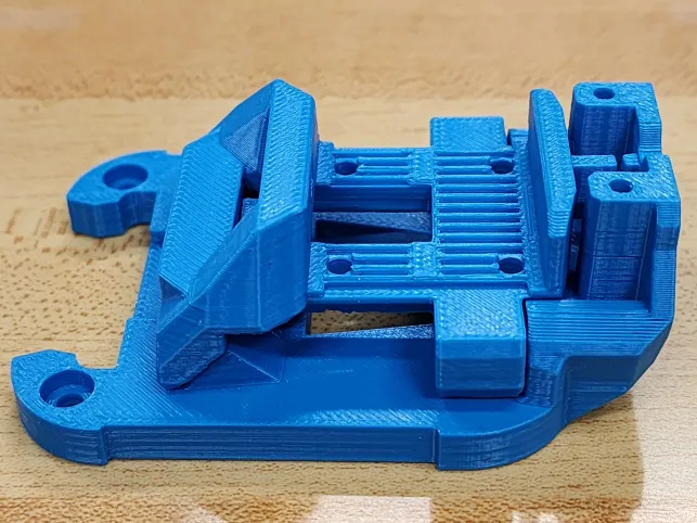
Welcome back, tech enthusiasts! Today, we’re diving into the Voron 2.x Mod known as StealthChanger—an evolving toolchanger modification from the Tapchanger. Currently a work in progress, the StealthChanger sets itself apart by opting for bushings and pins instead of the conventional bearings. In this brief exploration, we’ll highlight their unique design and the potential it holds for reshaping the capabilities of Voron 2.x models.
The StealthChanger introduces a unique perspective on toolchanger capabilities for Voron 2.x models by replacing the bearings of the Tapchanger with bushings and pins. This departure is anticipated to yield advantages such as reduced friction and smoother movements while reducing weight. While still in the works, the mod’s innovative design is being closely monitored by the Voron community, eager to witness its promise of enhanced durability and robustness while simple in design.
StealthChanger Printed Parts (Dragonburner) by ZombieHedgehogTapChanger Mechanism
Crucially, it’s worth noting that the StealthChanger is a work in progress. As is customary with developing technology, refinements may be needed before it reaches its full potential. Currently, compatibility extends only to the standard Stealth Burner tool, with plans to incorporate Mini Stealth Burner, Dragon Burner, and XOL tools in the future. For now, StealthChanger docks and klipper config are sourced from the Tapchanger repository until StealthChanger establishes its own. The Voron community actively participates in the evolution of this mod, contributing valuable feedback to enhance its functionality.
Tapchanger on the other-hand is stable at revision 3.1. It can fit 6 Dragon Burner toolheads on a 350mm Voron frame. Though the normal stealthburner toolhead can still be used, limiting number of toolheads. Through multiple subtypes exist, each one provides different rigidness, but trades off assembly difficulty. The plate type is very rigid compared to rods version, while square rods are in-between. Plate type will require more work to assemble in comparison to the others.
Tapchanger versions: Plates, Rods, & Square Rods
In the ever-evolving world of 3D printing, Voron’s StealthChanger & Tapchanger mods introduces a fresh perspective on toolchanger capabilities. With its departure from bearing designs and ongoing development, it holds the potential to redefine how Toolchangers handle tool changes. For enthusiasts, staying tuned to the StealthChanger’s progress promises an exciting journey filled with anticipation. Welcome to the next phase of Voron innovation!
Update (March 9th, 2024): Apologies, additional resistors are not required.Updated for Katapult (formerly Canboot)
This is a continuation from Part 1. We’ll be setting up a basic CAN bus network with basic components.
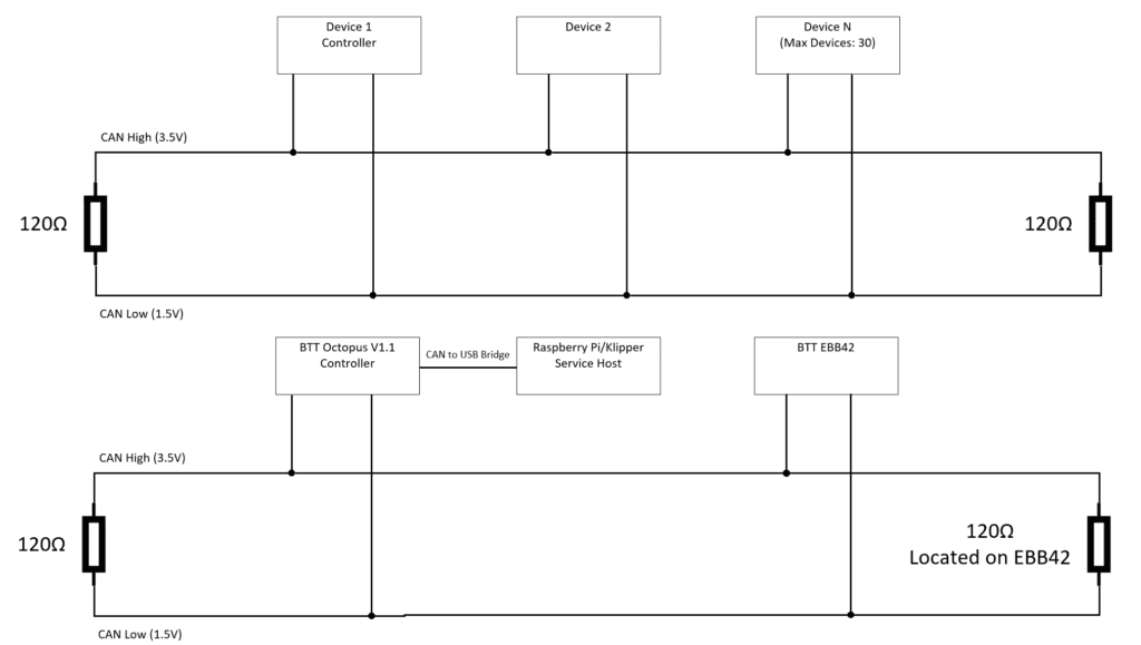
BTT Octopus and EBB42 without U2C Basic Setup
Note: Assuming Klipper git was previously installed at ~/klipper. Please note there are other methods to use CAN bus without BTT U2C, but will involve additional hardware at this time.
Hardware being used
Octopus (STM32F446)
EBB42 V1.2 (STM32G0B1)
RJ11/RJ12 end (Proper connector is RJ12, but only difference is pin count [4 vs 6])
Power Cables
EBB42 V1.2 has maximum of 5A pull. The printer environment we’ll be using is a Voron 2.4r2 and it uses 24V. We estimate maximum 8 ft of cable from the power source. After using two online calculators provided by https://www.omnicalculator.com/physics/dc-wire-size and https://www.wirebarn.com/Wire-Calculator-_ep_41.html with using 6 Amps for higher tolerance, 18 AWG stranded copper cable would work. Unfortunately, we didn’t have 18 AWG stranded copper cable on hand, thus we’ll be using stranded 16 AWG Aluminum cable for power delivery that we had in our inventory.
CAN BUS Signal Cables
For CAN bus, it is recommended to use twisted data bus to enhance its’ high noise immunity and common-mode rejection. We’ll be using a twisted pair from a working CAT5e stranded cable. CAT5e cable contains 4 twisted pairs of cable.
Wiring
Above image is a typical CAN bus network, below its what logically it’ll look like.
We choose blue and blue/white stranded pair from the CAT5e cable and solid blue will be CAN high. On Octopus end of CAT5e cable, we added a RJ11/12 connector (used this external github reference). The RJ11/RJ12 end can be plugged into the BTT Octopus V1.1.After installing the twisted pair and power cable into the cable chains, we terminated the BTT EBB42 male Molex connector (#39-01-2040) with the diagram provided from Big Tree Tech at this external github reference. We also plugged in the 120R(Ω) jumper on the EBB42 as we weren’t planning on adding additional nodes/devices to the CAN bus network.
BTT Octopus Steps
We are using a STM32F446 Octopus V1.1 Board. Please check the MCU of your Octopus as your settings may be different.
Klipper Installation
Run the following commands:
cd ~/klipper
make menuconfig
Set the following settings:
[*] Enable extra low-level configuration options
Micro-controller Architecture (STMicroelectronics STM32)
Processor Model (STM32F446)
Bootloader offset (32KiB bootloader)
Clock Reference (12 MHz crystal)
Communication interface (USB to CAN bus bridge (USB on PA11/PA12)
Can Bus Interface (CAN bus (on PD0/PD1))
(1000000) CAN bus speed
Press q and then y.
Type make and confirm no errors occurs.
Our Octopus board was connected via USB, so we used:
sudo service klipper stop
make flash FLASH_DEVICE=/dev/serial/by-id/usb-Klipper_stm32f446xx_...
sudo service klipper start
Raspberry Pi/Klipper Service Host Setup
We will need to setup a CAN interface for Klipper service to interact with. To confirm that the firmware has been installed, run lsusb and one of the connections should show OpenMoko, Inc Geschwister Schneider CAN adapter.
Add /etc/network/interfaces.d/can0 file with the below contents
allow-hotplug can0
iface can0 can static
bitrate 1000000
up ifconfig $IFACE txqueuelen 2048
One liner:
echo 'allow-hotplug can0\niface can0 can static\nbitrate 1000000\nup ifconfig $IFACE txqueuelen 2048' | sudo tee /etc/network/interfaces.d/can0 > /dev/null
Then reboot the Raspberry Pi/Klipper service host.
EBB42 V1.2 Steps
We are using EBB42 V1.2, however a previous model version or versions have a flaw where the heater is turned on during flashing and caused fire damage. Double check your version with the manufacture and take necessary precaution steps if required.
If CAN bus connection is connected to EBB, remove this CAN bus connection.
Important: If you skip this step, you will damage your EBB42.
Place jumper on USB-C power.
Plug in USB-C cable between Klipper host and EBB.
Power LED should be on by this step.
Hold down boot button and reset button, then release reset button, then release boot button.
Type lsusb and hit enter.
Output text should have a STM and DFU for a single USB device. After ID there will be text formatted as ####:#### this will be referred to as <uuid> in the Katapult Install steps.
Katapult Install
Run following commands:
git clone https://github.com/arksine/Katapult
cd Katapult
make menuconfig
Match settings below:
Micro-controller Architecture (STMicroelectronics STM32)
Processor model (SMT32G0B1)
Build CanBoot deployment application (Do not Build)
Clock Reference (8 MHz crystal)
Communication interface (CAN bus (on PB0/PB1))
Application start offset (8KiB offset)
(1000000) CAN bus speed
() GPIO pins to set on bootloader entry
[*]Support bootloader entry on rapid double click of reset button
[] Enable bootloader entry on button (or gpio) state
[] Enable Status LED
press q and y.
Type the below commands and replace <uuid> from the previous EBB42 step 6.
make
sudo dfu-util -a 0 -D ~/Katapult/out/katapult.bin --dfuse-address 0x08000000:force:mass-erase -d <uuid>
Disconnect USB-C cable and remove USB-C power jumper.
Important: If you skip this step, you will damage your EBB42.
Reconnect CAN bus cable.
Klipper Install
These are steps involved to install Klipper on top of CanBoot for EBB42.
Type the following commands:
cd ~/klipper
make menuconfig
Set the following settings:
[*] Enable extra low-level configuration options
Micro-controller Architecture (STMicroelectronics STM32)
Processor Model (STM32G0B1)
Bootloader offset (8KiB bootloader)
Clock Reference (8 MHz crystal)
Communication interface (CAN bus (on PB0/PB1)
(1000000) CAN bus speed
Press q and y.
Run the following:
make
python3 ~/katapult/scripts/flash_can.py -q -i can0
From the previous output, there will be a line formatted like Detected UUID: ############, Application: CanBoot use the ############ portion for the <EBB UUID> going forward.
There will be another UUID listed with Application: Klipper, use this for <Octopus UUID> going forward.
Download the example *.cfg for your EBB. For our case we downloaded bigtreetech-ebb-canbus-v1.2.cfg from https://github.com/bigtreetech/EBB and uploaded it into the Klipper configurations folder.
We added [include bigtreetech-ebb-canbus-v1.2.cfg] to the top of printer.cfg.
Want to setup Klipper’s input shaper, but don’t have a Raspberry Pi Pico on hand for a separate Klipper MCU? This article will step through using an Arduino Nano instead. A separate Klipper MCU in this context would allow you to run input shaper on multiple 3D printers by USB without requiring a dedicated ADXL345 sensor on each printer and reducing costs.
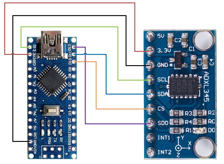
Wiring
Solder these pins together.
ADXL345
Arduino Nano
3V3/VCC
3.3V/VCC
GND
GND
CS
D10
SDO
D12
SDA
D11
SCL
D13
Flashing
Connect the Arduino Nano to the Klipper Host, in our case a Raspberry Pi 4. In order for us to flash the Arduino Nano from our Raspberry Pi 4. At this time of writing, there is a bug in avrdude used to flash and we will need to add a previous APT repo.
sudo nano /etc/apt/sources.list
Add deb http://raspbian.raspberrypi.org/raspbian/ buster main contrib non-free rpi
Save and quit (:wq)
sudo nano /etc/apt/preferences.d/avr-buster
Type below and save file Package: avr-libc avrdud binutils-avr gcc-avr Pin: release n=buster Pin-Priority: 1001
Change Micro-controller Architecture to Atmega AVR and Processor model to atmega328p
Press q and y
make clean
make
avrdude -patmega328p -c arduino -b 57600 -P /dev/ttyUSB1 -v -D -Uflash:w:out/klipper.elf.hex:i Note: /dev/ttyUSB1 may be different on your system and per printer primary MCU. Change any reference to match further ahead.
Once this is completed, nano will be ready to be used as a Second Klipper MCU
Update 8/31/2023: For those whom wish to copy and paste into a terminal:
Steps 1-7 – Revert to older avrdude. Note: we didn’t test the newer version and may be fixed.