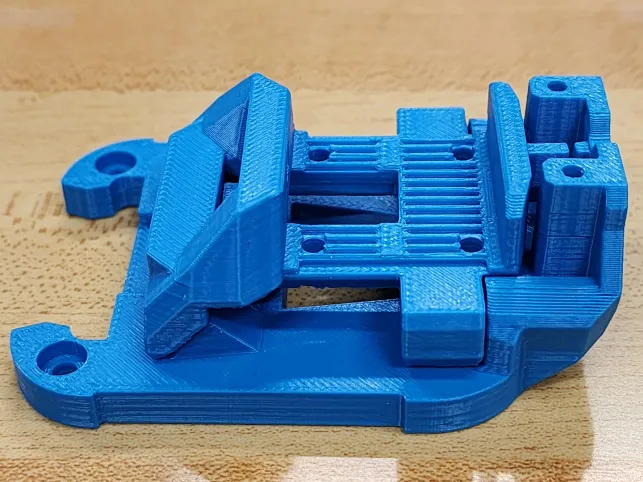
Welcome back, tech enthusiasts! Today, we’re diving into the Voron 2.x Mod known as StealthChanger—an evolving toolchanger modification from the Tapchanger. Currently a work in progress, the StealthChanger sets itself apart by opting for bushings and pins instead of the conventional bearings. In this brief exploration, we’ll highlight their unique design and the potential it holds for reshaping the capabilities of Voron 2.x models.
The StealthChanger introduces a unique perspective on toolchanger capabilities for Voron 2.x models by replacing the bearings of the Tapchanger with bushings and pins. This departure is anticipated to yield advantages such as reduced friction and smoother movements while reducing weight. While still in the works, the mod’s innovative design is being closely monitored by the Voron community, eager to witness its promise of enhanced durability and robustness while simple in design.
StealthChanger Printed Parts (Dragonburner) by ZombieHedgehogTapChanger Mechanism
Crucially, it’s worth noting that the StealthChanger is a work in progress. As is customary with developing technology, refinements may be needed before it reaches its full potential. Currently, compatibility extends only to the standard Stealth Burner tool, with plans to incorporate Mini Stealth Burner, Dragon Burner, and XOL tools in the future. For now, StealthChanger docks and klipper config are sourced from the Tapchanger repository until StealthChanger establishes its own. The Voron community actively participates in the evolution of this mod, contributing valuable feedback to enhance its functionality.
Tapchanger on the other-hand is stable at revision 3.1. It can fit 6 Dragon Burner toolheads on a 350mm Voron frame. Though the normal stealthburner toolhead can still be used, limiting number of toolheads. Through multiple subtypes exist, each one provides different rigidness, but trades off assembly difficulty. The plate type is very rigid compared to rods version, while square rods are in-between. Plate type will require more work to assemble in comparison to the others.
Tapchanger versions: Plates, Rods, & Square Rods
In the ever-evolving world of 3D printing, Voron’s StealthChanger & Tapchanger mods introduces a fresh perspective on toolchanger capabilities. With its departure from bearing designs and ongoing development, it holds the potential to redefine how Toolchangers handle tool changes. For enthusiasts, staying tuned to the StealthChanger’s progress promises an exciting journey filled with anticipation. Welcome to the next phase of Voron innovation!
Update (March 9th, 2024): Apologies, additional resistors are not required.Updated for Katapult (formerly Canboot)
This is a continuation from Part 1. We’ll be setting up a basic CAN bus network with basic components.
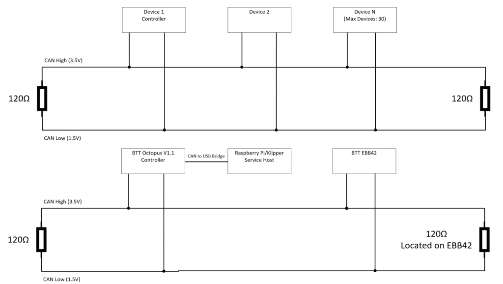
BTT Octopus and EBB42 without U2C Basic Setup
Note: Assuming Klipper git was previously installed at ~/klipper. Please note there are other methods to use CAN bus without BTT U2C, but will involve additional hardware at this time.
Hardware being used
Octopus (STM32F446)
EBB42 V1.2 (STM32G0B1)
RJ11/RJ12 end (Proper connector is RJ12, but only difference is pin count [4 vs 6])
Power Cables
EBB42 V1.2 has maximum of 5A pull. The printer environment we’ll be using is a Voron 2.4r2 and it uses 24V. We estimate maximum 8 ft of cable from the power source. After using two online calculators provided by https://www.omnicalculator.com/physics/dc-wire-size and https://www.wirebarn.com/Wire-Calculator-_ep_41.html with using 6 Amps for higher tolerance, 18 AWG stranded copper cable would work. Unfortunately, we didn’t have 18 AWG stranded copper cable on hand, thus we’ll be using stranded 16 AWG Aluminum cable for power delivery that we had in our inventory.
CAN BUS Signal Cables
For CAN bus, it is recommended to use twisted data bus to enhance its’ high noise immunity and common-mode rejection. We’ll be using a twisted pair from a working CAT5e stranded cable. CAT5e cable contains 4 twisted pairs of cable.
Wiring
Above image is a typical CAN bus network, below its what logically it’ll look like.
We choose blue and blue/white stranded pair from the CAT5e cable and solid blue will be CAN high. On Octopus end of CAT5e cable, we added a RJ11/12 connector (used this external github reference). The RJ11/RJ12 end can be plugged into the BTT Octopus V1.1.After installing the twisted pair and power cable into the cable chains, we terminated the BTT EBB42 male Molex connector (#39-01-2040) with the diagram provided from Big Tree Tech at this external github reference. We also plugged in the 120R(Ω) jumper on the EBB42 as we weren’t planning on adding additional nodes/devices to the CAN bus network.
BTT Octopus Steps
We are using a STM32F446 Octopus V1.1 Board. Please check the MCU of your Octopus as your settings may be different.
Klipper Installation
Run the following commands:
cd ~/klipper
make menuconfig
Set the following settings:
[*] Enable extra low-level configuration options
Micro-controller Architecture (STMicroelectronics STM32)
Processor Model (STM32F446)
Bootloader offset (32KiB bootloader)
Clock Reference (12 MHz crystal)
Communication interface (USB to CAN bus bridge (USB on PA11/PA12)
Can Bus Interface (CAN bus (on PD0/PD1))
(1000000) CAN bus speed
Press q and then y.
Type make and confirm no errors occurs.
Our Octopus board was connected via USB, so we used:
sudo service klipper stop
make flash FLASH_DEVICE=/dev/serial/by-id/usb-Klipper_stm32f446xx_...
sudo service klipper start
Raspberry Pi/Klipper Service Host Setup
We will need to setup a CAN interface for Klipper service to interact with. To confirm that the firmware has been installed, run lsusb and one of the connections should show OpenMoko, Inc Geschwister Schneider CAN adapter.
Add /etc/network/interfaces.d/can0 file with the below contents
allow-hotplug can0
iface can0 can static
bitrate 1000000
up ifconfig $IFACE txqueuelen 2048
One liner:
echo 'allow-hotplug can0\niface can0 can static\nbitrate 1000000\nup ifconfig $IFACE txqueuelen 2048' | sudo tee /etc/network/interfaces.d/can0 > /dev/null
Then reboot the Raspberry Pi/Klipper service host.
EBB42 V1.2 Steps
We are using EBB42 V1.2, however a previous model version or versions have a flaw where the heater is turned on during flashing and caused fire damage. Double check your version with the manufacture and take necessary precaution steps if required.
If CAN bus connection is connected to EBB, remove this CAN bus connection.
Important: If you skip this step, you will damage your EBB42.
Place jumper on USB-C power.
Plug in USB-C cable between Klipper host and EBB.
Power LED should be on by this step.
Hold down boot button and reset button, then release reset button, then release boot button.
Type lsusb and hit enter.
Output text should have a STM and DFU for a single USB device. After ID there will be text formatted as ####:#### this will be referred to as <uuid> in the Katapult Install steps.
Katapult Install
Run following commands:
git clone https://github.com/arksine/Katapult
cd Katapult
make menuconfig
Match settings below:
Micro-controller Architecture (STMicroelectronics STM32)
Processor model (SMT32G0B1)
Build CanBoot deployment application (Do not Build)
Clock Reference (8 MHz crystal)
Communication interface (CAN bus (on PB0/PB1))
Application start offset (8KiB offset)
(1000000) CAN bus speed
() GPIO pins to set on bootloader entry
[*]Support bootloader entry on rapid double click of reset button
[] Enable bootloader entry on button (or gpio) state
[] Enable Status LED
press q and y.
Type the below commands and replace <uuid> from the previous EBB42 step 6.
make
sudo dfu-util -a 0 -D ~/Katapult/out/katapult.bin --dfuse-address 0x08000000:force:mass-erase -d <uuid>
Disconnect USB-C cable and remove USB-C power jumper.
Important: If you skip this step, you will damage your EBB42.
Reconnect CAN bus cable.
Klipper Install
These are steps involved to install Klipper on top of CanBoot for EBB42.
Type the following commands:
cd ~/klipper
make menuconfig
Set the following settings:
[*] Enable extra low-level configuration options
Micro-controller Architecture (STMicroelectronics STM32)
Processor Model (STM32G0B1)
Bootloader offset (8KiB bootloader)
Clock Reference (8 MHz crystal)
Communication interface (CAN bus (on PB0/PB1)
(1000000) CAN bus speed
Press q and y.
Run the following:
make
python3 ~/katapult/scripts/flash_can.py -q -i can0
From the previous output, there will be a line formatted like Detected UUID: ############, Application: CanBoot use the ############ portion for the <EBB UUID> going forward.
There will be another UUID listed with Application: Klipper, use this for <Octopus UUID> going forward.
Download the example *.cfg for your EBB. For our case we downloaded bigtreetech-ebb-canbus-v1.2.cfg from https://github.com/bigtreetech/EBB and uploaded it into the Klipper configurations folder.
We added [include bigtreetech-ebb-canbus-v1.2.cfg] to the top of printer.cfg.
Setting up a computer network requires careful planning, and one important decision you’ll need to make is selecting the right patch cable lengths for the job. Patch cables are used to connect devices within a rack or between different racks, and choosing the right cable length is crucial to ensuring an efficient and easy-to-troubleshoot network.
When choosing patch cable lengths, it’s important to keep them short but not too short. For instance, 6-inch patch cables are ideal for connecting devices/patch panel ports within a single rack unit (U), which is 1.75 inches tall. Longer cables will create clutter and strain on the cable. A 1-foot patch cable is usually sufficient for as many as six rack units.
However, calculating the appropriate cable length can be more complex when the path goes in different directions or depths within the rack. In such cases, you’ll need to calculate the cable length based on the total inches required for the path. For instance, if the path goes in either horizontal direction, add 19 inches to the total vertical inches, then divide by 12 inches to obtain the cable length in feet. If the path goes from the front of the rack to the back, you’ll need to add the equipment depth to the total inches before calculating the cable length in feet.
Depending on the existing rack layout, it may also be necessary to add a service loop of 2-3 feet (24-36 inches) to allow for flexibility and future maintenance. Once you’ve determined the total cable length in feet, round up to the nearest foot. In some cases, it may be necessary to round up to the nearest foot ending with 5 or 0 when there is no pre-made cable length available that matches your requirements.
By following these guidelines, you can select the appropriate patch cable length for your computer network setup. This can help ensure optimal performance, efficiency, and easy maintenance, which are crucial for a successful network.
TLDR: Fast Formulas
Total Estimated Min Length (inches) = 1.75″ * (Rack U Height to Travel) + (if destination is not directly vertical from source in same rack, 19″) + (Device depth, if going from front to back of rack, commonly 21″) + (Any service loop required)
Total Min Length (Feet) = Round Up (Total Estimated Min Length (inches)/12)
The communication protocol, CAN bus, is used in various industries such as automotive, medical, and industrial systems. In the field of 3D printing, CAN bus has the potential to improve the printing process by connecting several components, including the main control board, extruders, and motors. CAN bususes high-speed serial communication to enable real-time communication, making it suitable for applications that require timing and synchronization.
The CAN protocol defines the way devices communicate over a CAN busnetwork, determining how data is transmitted and received, and how devices are addressed and identified. The protocol uses differential signaling to send data through two wires with equal and opposite voltage levels. The protocol can detect and correct transmission errors, ensuring reliable data transmission in noisy environments and over long distances.
Some Hardware Examples:
Main Controller Boards:
BigTreeTech(BTT) Octopus
Duet3D Main Board 6HC
Duet3D Main Board 6XD
Toolhead/extruders:
Duet 3 Tool Board 1LC
Duet 3 Tool Board 1HCL
BigTreeTech(BTT) EBB36 & EEB42 (Note: certain hardware versions may cause a fire, reach out to BTT support)
BigTreeTech(BTT) EBB U2C
Motors:
Duet 3 Expansion Board 3HC
Duet 3 Expansion Board 1XD
Once at least 2 CAN bus compatible components had been bought, the process of connecting them via the CAN bus network can begin. CAN bus cables are required to link all components together. Typically, these cables have four wires – two for power and two for communication. One can either purchase these cables or create them using CAT3 or higher-rated cables for the communication wires and appropriate AWG-gauge wires for the power wires if they choose to make them themselves.
After connecting the components, one needs to configure the firmware of the 3D printer to use CAN bus. This involves setting the correct baud rate, addressing scheme, and other parameters to ensure that the components can communicate effectively. Finally, one needs to test their setup to ensure that CAN bus communication is working correctly. This will involve sending commands to the printer and monitoring the responses to ensure that data is being transmitted accurately and reliably.
In case issues arise, some common issues that may occur include incorrect wiring, electrical noise, and software issues. Some resolutions to these issues, double-check all connections to ensure they are properly wired, reduce electrical noise by using shielded cables and ferrite beads, ensure the latest firmware is being used with all settings correctly configured, and ensuring correct resistance & voltage is used on CAN bus.
CAN bus enables fast and reliable communication between different components, allowing for greater control and precision in the printing process, resulting in higher-quality prints. Although implementing CAN bus in 3D printing may require additional hardware and configuration, the benefits are clear. By reducing the number of cables and simplifying the wiring of the printer, one can achieve faster printing speeds, possibly less toolhead weight, and improved reliability. Moreover, using CAN bus in 3D printing allows for scalability and expand-ability, which can accommodate future changes without requiring significant modifications to the network.
Want to setup Klipper’s input shaper, but don’t have a Raspberry Pi Pico on hand for a separate Klipper MCU? This article will step through using an Arduino Nano instead. A separate Klipper MCU in this context would allow you to run input shaper on multiple 3D printers by USB without requiring a dedicated ADXL345 sensor on each printer and reducing costs.
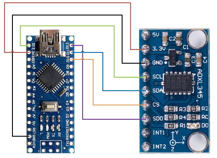
Wiring
Solder these pins together.
ADXL345
Arduino Nano
3V3/VCC
3.3V/VCC
GND
GND
CS
D10
SDO
D12
SDA
D11
SCL
D13
Flashing
Connect the Arduino Nano to the Klipper Host, in our case a Raspberry Pi 4. In order for us to flash the Arduino Nano from our Raspberry Pi 4. At this time of writing, there is a bug in avrdude used to flash and we will need to add a previous APT repo.
sudo nano /etc/apt/sources.list
Add deb http://raspbian.raspberrypi.org/raspbian/ buster main contrib non-free rpi
Save and quit (:wq)
sudo nano /etc/apt/preferences.d/avr-buster
Type below and save file Package: avr-libc avrdud binutils-avr gcc-avr Pin: release n=buster Pin-Priority: 1001
Change Micro-controller Architecture to Atmega AVR and Processor model to atmega328p
Press q and y
make clean
make
avrdude -patmega328p -c arduino -b 57600 -P /dev/ttyUSB1 -v -D -Uflash:w:out/klipper.elf.hex:i Note: /dev/ttyUSB1 may be different on your system and per printer primary MCU. Change any reference to match further ahead.
Once this is completed, nano will be ready to be used as a Second Klipper MCU
Update 8/31/2023: For those whom wish to copy and paste into a terminal:
Steps 1-7 – Revert to older avrdude. Note: we didn’t test the newer version and may be fixed.
Update: 15 December 2021 – version 6.5.54 and earlier is vulnerable. Please update Unifi Controller again.
With the recent Log4j vulnerability, CVE-2021-442228, UniFi controller version 6.5.54 and earlier is vulnerable.
Jacobalberty has backported the fix to v6.0.45 and v5.14.23 for those whom are on the older hardware or controller versions.
For ours, we will be migrating to the latest v6 build by changing out Docker tag to “jacobalerty/unifi:v6” instead of “jacobalerty/unifi:stable-6” by following UniFi Controller – Docker Tag Change again with the tag changed.
While checking up on our UniFi controller image for updates, the tag “jacobalberty/unifi:stable” is no longer valid. There are 2 new tags instead, “jacobalerty/unifi:stable-5″ and ” jacobalerty/unifi:stable-6″. We will be upgrading to UniFi controller 6 with the tag “jacobalerty/unifi:stable-6.
WARNING: Upgrading the controller may invoke device provisioning, which may disrupt current service/s.
As a precaution, download a backup of the controller by going to Settings > Backup > Download Backup.
After a minute of executing the last command, check the Unifi Controller web interface and everything works. Devices will start to re-provision.
If this is successful, run the below command for cleanup
docker rm unifi.old
If this fails, suggest starting over and restore the controller docker image with the backup that was downloaded at the beginning. Be sure to clean up the docker storage folder on the host prior.
Ever wanted to connect to a remote server or host and tired of typing a password and worrying about password attacks. The solution is to use SSH key pairs, we will be covering SSH key pair authentication setup.
In addition, passwords shouldn’t be used in today production environments as they are typically weak in comparison with a public and private key pair. Multi-factor authentication should also be used, however this post will not be covering this setup.
SSH Key Pair Generation
To generate these keys, you will use ssh-keygen. Do not use RSA or DSA, they are weak, the strongest encryption key out at the moment is ed25519.
ssh-keygen -a 10000 -t ed25519 -f ~/.ssh/id_ed25519 -C “Nate15329”
If you use a long and strong passphrase, this will avoid from someone using these keys if they ever got a copy. You will need to type in the passphrase like a password when remoting in, but also the SSH key is also validated.
Remote System Setup
Next is preparing and copying the public key to the remote system that is being accessed. Never copy the private key to another system.Public keys end with .pub extension and only these are to be copied to remote systems.
Ensure the remote system has the following folder structure and file preexisting for the account. Below are the commands to get these setup.
While setting up our Raspberry Pis, one of the things that we usually setup is Log2Ram. The entire goal of this project is to extend the SD storage life.
By default Raspberry Pi stores logs on the SD card, however SD cards have limited write cycles due to being FLASH based storage. Once this limit has been reached, it will fail. Log2Ram forces logs to be stored in memory (RAM) by changing /var/log to a RAM disk and once every day to reduce writing and increase lifespan of the SD card.
Highly recommend for any environment running off of an SD card, along with configuration and sending logs to a central logging system such as syslog. We won’t be covering the central logging, but recommended for production environments.
Installation is pretty straight forward.
git clone https://github.com/azlux/log2ram.git
cd log2ram
chmod +x install.sh
sudo ./install.sh
Usually I edit /etc/log2ram.conf to set size to 128 MB instead of default 40MB by using sudo nano /etc/log2ram.conf
SIZE=128MB
Then a restart would be need to be done to make this become in effect by sudo reboot
With future updates, I suggest following the advice that is in the README file. Usually, we would need to manually stop the service prior to running the update.
We had upgraded our Ender 3 to Marlin 2.0.5.3, this will provide the steps that we did. As noted, we are using the MKS Gen L board and not the board the Ender 3 comes with.
With the new Marlin firmware, it is better in our opinion to compile it via PlatformIO in Visual Studio Code than in the Arduino IDE. It is recommended to record any values stored such as current z-offset, extrusion settings, etc before flashing the updated firmware as these values will need to be placed back afterwards.
Environment Setup
Please follow these steps to setup the environment:
Install the following extensions: PlatformIO (by PlatformIO) & Auto Build Marlin (by Marlin Firmware)
Relaunch Visual Studio Code.
Download Marlin Firmware Version 2.0.5.3 from https://marlinfw.org/ and extract the zip folder.
Download the Ender-3 configuration from the Github repo as well: Link
Configuration
Let’s get started with configuring the project:
Place the Ender 3 example config files (configuration.h and configuration_adv.h, optional _Bootscreen.h and _Statusscreen.h) that was downloaded under step 4 under Marlin/src directory.
Click on the PlatformIO module in Visual Studio Code, click open project and select the directory where the platformio.ini file is located
Modify the configuration.h as follows:
Remove #define CONFIG_EXAMPLES_DIR "Creality/Ender-3/CrealityV1" line, it may have a different path
If the _Bootscreen.h and/or _Statusscreen.h has been copied; either to un-comment or comment (//) the lines beginning with associated lines beginning with #define SHOW_CUSTOM_BOOTSCREEN and/or #define CUSTOM_STATUS_SCREEN_IMAGE
Change line from #define MOTHERBOARD BOARD_MELZI_CREALITY to #define MOTHERBOARD BOARD_MKS_GEN_L
Change the stepper directions to opposite; end result values should be: #define INVERT_X_DIR false , #define INVERT_Y_DIR false ,& #define INVERT_Z_DIR true
Change the extruder direction to the opposite; end result value should be #define INVERT_E0_DIR false
Make any additional changes you may need for your setup.
Modify the Configuration_adv.h as below:
Set the line #define E0_AUTO_FAN_PIN to #define E0_AUTO_FAN_PIN 7
Building the firmware
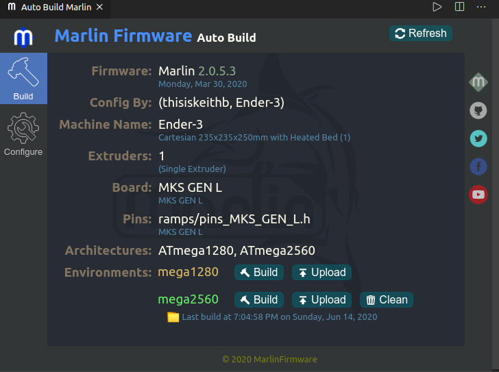
To build the firmware, the Marlin Auto Build extension will be used in Visual Studio Code:
On the Marlin Firmware Auto Build extension, click Refresh button. The values will be updated to what is in the configuration files.
Click on the Build button next to mega2560 ; this should give a succeeded message in the terminal output. If it doesn’t give a success message, please review the configuration files for configuration issues.
On successful build, plug in the MKS Gen L board via USB and press the Upload button.
After the upload, don’t forget to place back any custom values prior.
A good practice is to archive this firmware somewhere (plus a simple date stamp) where it can be used as a future reference to newer Marlin firmware versions.