Klipper – Input Shaper w/ Arduino Nano

Want to setup Klipper’s input shaper, but don’t have a Raspberry Pi Pico on hand for a separate Klipper MCU? This article will step through using an Arduino Nano instead. A separate Klipper MCU in this context would allow you to run input shaper on multiple 3D printers by USB without requiring a dedicated ADXL345 sensor on each printer and reducing costs.

Wiring

Solder these pins together.
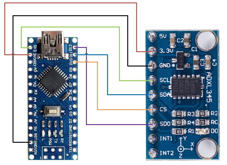
ADXL345Arduino Nano
3V3/VCC3.3V/VCC
GNDGND
CSD10
SDOD12
SDAD11
SCLD13

Flashing

Connect the Arduino Nano to the Klipper Host, in our case a Raspberry Pi 4. In order for us to flash the Arduino Nano from our Raspberry Pi 4. At this time of writing, there is a bug in avrdude used to flash and we will need to add a previous APT repo.

  1. sudo nano /etc/apt/sources.list
  2. Add deb http://raspbian.raspberrypi.org/raspbian/ buster main contrib non-free rpi
  3. Save and quit (:wq)
  4. sudo nano /etc/apt/preferences.d/avr-buster
  5. Type below and save file
    Package: avr-libc avrdud binutils-avr gcc-avr
    Pin: release n=buster
    Pin-Priority: 1001
  6. Save and quit (:wq)
  7. sudo apt update
    sudo apt install avr-libc avrdude binutils-avr gcc-avr
  8. cd ~/klipper
  9. make menuconfig
  10. Change Micro-controller Architecture to Atmega AVR and Processor model to atmega328p
  11. Press q and y
  12. make clean
    make
  13. avrdude -patmega328p -c arduino  -b 57600 -P /dev/ttyUSB1 -v  -D -Uflash:w:out/klipper.elf.hex:i
    Note: /dev/ttyUSB1 may be different on your system and per printer primary MCU. Change any reference to match further ahead.
  14. Once this is completed, nano will be ready to be used as a Second Klipper MCU

Update 8/31/2023: For those whom wish to copy and paste into a terminal:

Steps 1-7 – Revert to older avrdude. Note: we didn’t test the newer version and may be fixed.

sudo sed -i '$ a\deb http://raspbian.raspberrypi.org/raspbian/ buster main contrib non-free rpi' /etc/apt/sources.list

echo -e "Package: avr-libc avrdude binutils-avr gcc-avr\nPin: release n=buster\nPin-Priority: 1001" | sudo tee /etc/apt/preferences.d/avr-buster > /dev/null

sudo apt update

sudo apt install avr-libc avrdude binutils-avr gcc-avr

Steps 8-13

cd ~/klipper
make menuconfig
make clean
make
avrdude -patmega328p -c arduino  -b 57600 -P /dev/ttyUSB1 -v  -D -Uflash:w:out/klipper.elf.hex:i

Klipper Config

  1. Add a config file called adxl.cfg under the Klipper config section for each printer.
  2. Add the following lines:
[mcu arduino_nano_adxl]
serial: /dev/ttyUSB1

[adxl345]
cs_pin: arduino_nano_adxl:PB2

[resonance_tester]
accel_chip: adxl345
probe_points:
100,100,30
  1. Press save & close
  2. Add [include adxl.cfg] to printer.cfg
    Note: if it is not connected to the printer add a # in front of it to disable
  3. Press save & restart

Ender 3 – MKS Gen L – Marlin 2.0.5.3 Upgrade

We had upgraded our Ender 3 to Marlin 2.0.5.3, this will provide the steps that we did. As noted, we are using the MKS Gen L board and not the board the Ender 3 comes with.

With the new Marlin firmware, it is better in our opinion to compile it via PlatformIO in Visual Studio Code than in the Arduino IDE. It is recommended to record any values stored such as current z-offset, extrusion settings, etc before flashing the updated firmware as these values will need to be placed back afterwards.

Environment Setup

Please follow these steps to setup the environment:

  1. Install Microsoft’s Visual Studio Code from https://code.visualstudio.com/
  2. Install the following extensions: PlatformIO (by PlatformIO) & Auto Build Marlin (by Marlin Firmware)
  3. Relaunch Visual Studio Code.
  4. Download Marlin Firmware Version 2.0.5.3 from https://marlinfw.org/ and extract the zip folder.
  5. Download the Ender-3 configuration from the Github repo as well: Link

Configuration

Let’s get started with configuring the project:

  1. Place the Ender 3 example config files (configuration.h and configuration_adv.h, optional _Bootscreen.h and _Statusscreen.h) that was downloaded under step 4 under Marlin/src directory.
  2. Click on the PlatformIO module in Visual Studio Code, click open project and select the directory where the platformio.ini file is located
  3. Modify the configuration.h as follows:
    1. Remove #define CONFIG_EXAMPLES_DIR "Creality/Ender-3/CrealityV1" line, it may have a different path
    2. If the _Bootscreen.h and/or _Statusscreen.h has been copied; either to un-comment or comment (//) the lines beginning with associated lines beginning with #define SHOW_CUSTOM_BOOTSCREEN and/or #define CUSTOM_STATUS_SCREEN_IMAGE
    3. Change line from #define MOTHERBOARD BOARD_MELZI_CREALITY to #define MOTHERBOARD BOARD_MKS_GEN_L
    4. Change the stepper directions to opposite; end result values should be: #define INVERT_X_DIR false , #define INVERT_Y_DIR false ,& #define INVERT_Z_DIR true
    5. Change the extruder direction to the opposite; end result value should be #define INVERT_E0_DIR false
    6. Make any additional changes you may need for your setup.
  4. Modify the Configuration_adv.h as below:
    1. Set the line #define E0_AUTO_FAN_PIN to #define E0_AUTO_FAN_PIN 7

Building the firmware

To build the firmware, the Marlin Auto Build extension will be used in Visual Studio Code:

  1. On the Marlin Firmware Auto Build extension, click Refresh button. The values will be updated to what is in the configuration files.
  2. Click on the Build button next to mega2560 ; this should give a succeeded message in the terminal output. If it doesn’t give a success message, please review the configuration files for configuration issues.
  3. On successful build, plug in the MKS Gen L board via USB and press the Upload button.

After the upload, don’t forget to place back any custom values prior.

A good practice is to archive this firmware somewhere (plus a simple date stamp) where it can be used as a future reference to newer Marlin firmware versions.

3D Printer Calibration

Here’s what I use to calibrate our 3D printers. There are many guides out there for most of the methods and didn’t see the need to go into heavy details.

Calibration Tools used:

  • Pro-Grade Electronic Digital Caliper 82806
    • Know your accuracy tolerances, ours was +- .02 mm for lengths below 100mm with a resolution of .01 mm
  • Thin Wall Calibration https://www.thingiverse.com/thing:342198
  • Single sheet of paper

1.Initial Extruding Calibration

First thing we will need to calibrate on a new 3D printer is the filament extrude rate. It is very important to get this as accurate as possible, minor tweaking can be done with extrusion multipliers.

To figure this out by telling the printer to send 30 mm of filament through with the hot end disconnected and measuring with a caliper to see if the amount is accurate. Then update the stored value of Esteps/mm under Marlin Motion options by following this formula: Current Esteps/mm * 30mm / Actual amount of filament pushed

For example:

  • Current Esteps/mm: 93
  • Tell printer to extrude this amount of filament: 30mm
  • After measuring the amount of filament extruded: 29.33 mm
  • New Esteps/mm value = 93 * 30/29.33 = 95.124

2. Bed Leveling

Bed leveling is crucial for it will either allow your print complete properly or outright fail later on besides filament run-out or the disastrous thermal runaway. There are numerous ways of getting this done usually by sliding a piece of paper between the heated nozzle and heated bed, or something similar to a BLTouch or a conductive sensor.

The methods that are used often:

  1. 1st is done with piece of paper between heated nozzle and heated bed at normal printing temperatures for the printer. Since I print mainly in PLA, the temps would be at 200 C and bed at 70 C. Then manually level the middle, then the 4 corners where the paper is slightly catching between extruder and the bed
  2. Next, print Bed Leveling squares that looks like the 5 dot side on dice, 1 mm height and slightly adjust our leveling while it prints and wait a few lines are printed after adjusting and see if its flat and clean looking and doesn’t come off of the bed easily. An example of these squares on Thingiverse: https://www.thingiverse.com/thing:2789086

For Auto Bed leveling, a great bed visual is from OctoPrint with the plugin Bed Visualizer. It will highlight which corners need to be readjusted much better and readjust the dark red and blue slightly. Just keep an eye on the visual scale as it will re-adjust.

3. Wall thickness

Next up to calibrate our Wall thickness, please note that this will affect your bed leveling, extrusion multiplier, and/or Esteps/mm. Essentially with .2 mm nozzle, print a hollow cube with .2 mm thick walls with a layer height of 0.16 mm (80% the size of the nozzle), then measuring with a caliber. A good resource to use are the Thin Wall calibration files created by MEH4d at https://www.thingiverse.com/thing:342198

Once the .2 mm thick walls have been printed, measure the wall thickness with the caliber but exclude the bottom of the walls. The bottom will usually be a tad off due to 1st layer height/bed leveling is a tad off. If the thickness is off try adjusting the multiplier between .9 and 1.1, but keep in mind of your calibers limits. For example, if the measured result was .19, you could be very will be accurate.

If you had to adjust your multiplier to get best results outside of this range, place the multiplier back to 1 and adjust your ESteps/mm. Lower if the walls were too thick and the opposite if the walls were thin. After readjusting, you may need to readjust the bed level and layer heights.

Usually, a good max layer height for each of the nozzle sizes are at 80% as shown below:

  • 0.2 mm nozzle = 0.16 mm layer height
  • 0.3 mm nozzle = 0.24 mm layer height
  • 0.4 mm nozzle = 0.32 mm layer height
  • 0.5 mm nozzle = 0.40 mm layer height
  • 0.6 mm nozzle = 0.48 mm layer height

4. XYZ Calibration Cube

At this point, print a calibration cube and measure with the caliber. Usually, it’ll be within measured dimensions that are to be expected. Check how the cube looks by actually looking for infill, speed, and other issues and try to correct them in our slicer program. Slowing down the speed improves many issues at this point.

5. Stress Test

Now its time to stress test your printer. Good set of models to use are by ctrlV on Thingiverse especially https://www.thingiverse.com/thing:704409 and then part fitting a M4 nut in the slot. Also, look at how well the filament retraction works and increase or decrease the retraction length.

Nate15329's Blog