UniFi Controller – Self Hosted Docker

One of the wifi access point brands that we’ve always recommend to family, friends, and others is Unifi. Usually, we end up having to do maintenance of their equipment. A solution is to setup an Unifi Docker container for a L3 management over the internet. Sure, we could set it up to phone home to UniFi cloud management, but what would be the fun of that?

We would like to note that we are not Docker experts or work with Docker on a daily basis and it’s something we would like to study more into when we have the chance. We are sure there is a more automated way to maintain the Docker image.

Step 1: On a Linux host, add a service account for Docker. Doesn’t need to be the same name. After adding the user, get the UID of the user, this will be referenced later.
sudo adduser docker_unifi

Step 2: Install Docker
curl -fsSL get.docker.com -o get-docker.sh
sh get-docker.sh

Step 3: Setup persistent storage.
sudo mkdir -p /var/docker_storage/unifi
sudo chown docker_unifi:docker_unifi /var/docker_storage/unifi

Step 4: Pull and create Docker Container

I’ll be using Jacob Albery’s container for Unifi. Use a container that you trust, at this time of this post, there was no official Unifi container.
docker pull jacobalberty/unifi:stable

To create the container, we will need the UID and GID of the non root user you’ve created in Step 1.
id -u docker_unifi
id -g docker_unifi

In this case, the UID and GID of docker_unifi is 1001.

The below command will create the Docker container and allow it to automatically restart if it ever crash and will not run as root. In this case, we are using L2 discovery to setup and firmware upgrade the APs on the local network. Otherwise, we would use network port forwarding.
docker run -d --restart=always --net=host --name=unifi -e RUNAS_UID0=false -e UNIFI_UID=1001 -e UNIFI_GID=1001 -v /var/docker_storage/unifi:/unifi jacobalberty/unifi:stable

To update this container in the future, use the following commands. Just be sure to remember what you used for creating the Docker container.

docker pull jacobalberty/unifi:stable
docker stop unifi
docker rename unifi unifi.old
docker run -d --restart=always --net=host --name=unifi -e RUNAS_UID0=false -e UNIFI_UID=1001 -e UNIFI_GID=1001 -v /var/docker_storage/unifi:/unifi jacobalberty/unifi:stable

If the upgrade was successful, remove the old container by using command:
docker rm unifi.old

Next is setting up external DNS.

External DNS – Setup

Since normal consumer external IP addresses usually change every so often and we needed to allow the firewall to only allow certain IP addresses as a source. An A or AAAA record will be needed to be updated dynamically by a client at the client’s location.

Luckily, we are able to setup the DDNS settings at these locations, each with their own unique API key following a naming convention and under a different domain name than the primary one utilized. If the client has a public domain name already, see if you can get them to setup DDNS on public DNS instead. We are using Cloudflare DNS nameservers and protections; this will be different depending on what you use.

We suggest making a subdomain that you only know and add sub-records to that.

For example:

  • A record for 1 client site
    • Host Name: c1.u.i
    • Proxy status: DNS only (do not use proxied, your firewall will block these)
  • A record for another client site
    • Host Name: c2.u.i
    • Proxy status: DNS only

If DDNS is configured correctly, the DNS records update with the correct IP addresses. Next we configure the firewall to only allow these certain FQDN.

Firewall – Setup

We use pfSense firewall here and the easiest way to setup the firewall settings and not having multiple repeating rules is to setup an Firewall Alias for both the Ports and Hosts allowed. Below is an example of the Hosts alias.

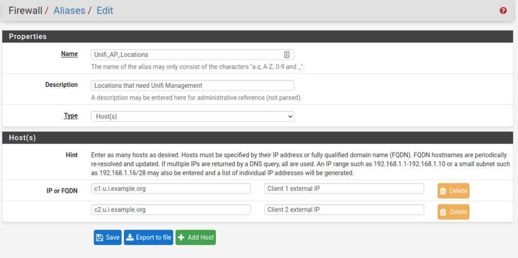
In the firewall rules, we set the Hosts Alias as the source, the destination, and the Port Alias for the allowed custom Ports. This would prevent usual internet background scans and malicious users/bots from seeing the ports are open.

As always, secure this environment with firewalls and within a DMZ network zone that is separate from your normal network and always keep this host and the Docker image updated. We allowed the following ports through the firewall defined here: https://help.ubnt.com/hc/en-us/articles/218506997-UniFi-Ports-Used#2

UniFi Controller – Setup

Be sure to set the Controller hostname to the FQDN and check the box to Override inform host with Controller Hostname/IP. Also, update this public DNS record to point to the Controller WAN IP address.

To remove/migrate a external client

  1. Migrate their Unifi Management 1st. Note: Site Export works wonders.
  2. Notify the DDNS record is no longer required (unless they set it up and want to keep it)
  3. If any, remove their public DNS entries & their DNS API access to your domain management
  4. Remove the FQDN name from the firewall host alias.

MikroTik Switch – Setup VLANs

I had purchased a MikroTik RB260GS (product link) to allow me to setup vlans for about $40 and later be able to setup a fiber run for a few remote devices.The MikroTik RB260GS is able to handle 802.1Q VLAN tags with 5 Gigabit Ethernet Ports and a single SPF cage. It can be powered by PoE (Power over Ethernet) on the 1st port and has a small form factor of 4 7/16 x 5 1/2 x 1 1/8 inches or 133 x 139 x 28 mm. There are larger and different models to choose from as well and should be considered depending on your needs.

From the beginning of trying to setup the VLANs, I had a hard time with this switch and a learning curve ahead of me for this solution. I hope this will assist those whom are having difficulties as well.

Port – Trunk

A trunk port is where multiple VLANs share the same physical connection and is used for the network backbone infrastructure up to the Access Level Switches.

Also, consider the amount of VLANs and traffic going through this port, it will be limited to 1 Gigabit and shared amongst all the VLANs going through it. Sometimes, it might be a better idea to have the SPF port be the trunk port with a 10 Gb fiber module. It would use less power, faster, lower latency, and electrically isolated from the other end of the trunk on this connection.

For this switch, it’s best for the trunk port to be port 1, especially if PoE is being delivered from another switch, or the SPF port. Below is how to configure the trunk port and can be any port on the switch.

  1. Navigate to VLAN tab
  2. Configure the port’s Ingress settings as listed:
    • VLAN Mode: Enabled
    • VLAN Recieve: Any
    • Default VLAN ID: 1
    • Force VLAN ID: Unchecked
  3. Configure the port’s Egress settings as listed:
    • VLAN Header: Add If Missing
  4. Navigate to VLANS tab , Add the VLAN numbers here.
  5. Make sure the Trunk port has all of the VLANs settings are set to Leave as is

Access Ports

These ports only have a single VLAN associated to them and is normally used at the Access Switch Level when end devices plug into.

  1. Navigate to VLAN tab
  2. Configure the port’s Ingress settings as listed:
    • VLAN Mode: Strict
    • VLAN Recieve: only untagged
    • Default VLAN ID: <Your VLAN ID here>
    • Force VLAN ID: Unchecked
  3. Configure the port’s Egress settings as listed:
    • VLAN Header: always strip
  4. Navigate to VLANS tab
  5. Make sure the Access port has all of the VLANs settings are set to Not a Member, except for the VLAN ID you’ve entered in step 2. It would be set to the value Always strip.

Multi-VLAN Ports

Sometimes there is a need where a port may need multiple VLANs going across it to a device, like a wireless access point. See below settings

  1. Navigate to VLAN tab
  2. Configure the port’s Ingress settings as listed:
    • VLAN Mode: Strict
    • VLAN Recieve: any
    • Default VLAN ID: <Your Default VLAN ID here, usually management VLAN ID>
    • Force VLAN ID: Unchecked
  3. Configure the port’s Egress settings as listed:
    • VLAN Header: always strip
  4. Navigate to VLANS tab
  5. Make sure this port has all of the VLANs settings are set to Leave as is except for the VLAN ID you’ve entered in step 2. This would be set to the value Always strip. The non-allowed VLANS on that port should be set to Not a Member

Testing your config

It’s best practice to test each port to see if the configuration is correct when doing this the 1st few times. Wireshark (link) will be your friend or even a simple checking of the IP range you receive will work for the most part. There are plenty of online tutorials with working with Wireshark and I will not cover them.

DDR4 RAM Latency

As a system builder, enthusiast, and gamer, we usually purchase for a new build is RAM (Random Access Memory). This RAM is used for fast temporary storage for your CPU (Central Processing Unit). RAM is similar to amount of desk’s top area. Persistence storage such as HDDs and SDDs are very slow to process data directly, plus they have a limited lifespan for reads and writes. These are like file cabinets. RAM is used between the CPU and the persistence storage, bringing faster application performance. We would want the fastest response RAM by looking at the lowest latency and including estimated cost per GB.

RAM is sold in terms of speed and CAS Latency. RAM speed is the built in clock cycles that refreshes the memory and is in terms of MHz or MT/s. CAS Latency is the delay time between memory controller asks for data and data is available on the RAMs output pins and usually is in nanoseconds.

Since RAM is sold with different speed and CAS Latency, the following formula will assist you on figuring out the relatively faster RAM as the 2 values determine the performance of the RAM.

Latency (ns) = Clock Cycle Time (ns) x CAS Latency (CL)

Latency (ns) = (1/Module Speed(MT/s) x 2) x CAS Latency (CL)

To find the higher performance RAM, look at the lowest CAS Latency and higher RAM speed to minimize the latency as much as possible. Shown below we calculated the latency. We’ve excluded some results due to not existing on the current market or only found very few results to provide an good average price per GB.

Officially, DDR4 memory limitation is set by JEDEC (https://www.jedec.org/) and the upper limit is at 3200 (MT/s) before needing to turn on XMP (Intel Extreme Memory Profile) in motherboard settings (BIOS/UEFI) to get the higher speeds on XMP Ready/Certified RAM. Some motherboards may not have this option to enable. Please refer to your motherboard specs/manual.

Module SpeedXMP Profile RequiredCAS LatencyLatency (ns)Est Price $/GB (6/2019)
4400Yes177.7320.937
4400Yes188.1819.749
3600Yes158.3316.281
4000Yes178.515.745
4400Yes198.6418.041
3200148.7511.149
3600Yes168.8912.292
4000Yes18911.619
3000149.338.923
3200159.389.895
3600Yes179.4410.635
4000Yes199.515.706
2666139.7511.697
300015108.61
320016108.932
3600Yes181010.754
3600Yes1910.566.484
30001610.677.868
24001310.836.906
26661511.257.023
30001711.335.577
24001411.676.454
266616126.582
21331312.196.242
24001512.57.432
21331413.139.76
24001613.335.82
21331514.067.466
24001714.177.164

The difference between the lowest and highest latency times are 7 nanoseconds apart. These differences might be noticeable, but very slightly.

As for our gamer audience, it is wiser to spend extra money on the GPU than on faster RAM. usually for gaming an individual computer only needs 8 to 16 GB depending on the game and near 10 ns in latency before getting higher prices.

Nate15329's Blog